
An electrical plan may look technical, but with a bit of explanation, you can read it yourself. Useful if you're renovating, buying a property, or simply want to understand how your installation works.
The electrical circuit diagram offers a schematic overview of the entire electrical installation of a home. This file is mandatory for an inspection (compliance check) and when selling a house.
It consists of two documents:
- a single-line diagram
- and a position diagram
Together, they provide a complete picture of your installation, from the fuse box to every socket.

What's on the plan
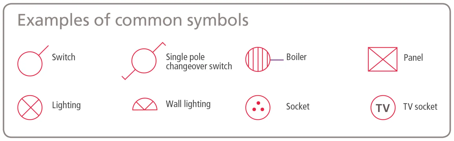
All symbols on an electrical plan are standardised according to Book 1 of the RGIE (Règlement Général des Installations Électriques, i.e. the Belgian General Regulations for Electrical Installations).This means that every installer and inspector speaks the same "language".
The symbols on the diagrams represent:
- The conduits and cables
- The connection points (sockets, light points)
- The fixed electrical appliances (such as an oven or water heater)
- The protection elements (circuit breakers, earthing, residual current devices, etc.)
The single-line diagram
The single-line diagram is the most abstract part. It doesn't show where everything is located in your home, but how the electrical circuits are connected to each other. Think of it as the technical family tree of your installation.
Letters for circuits
Every electrical circuit is assigned a letter (A, B, C...).
Important: A circuit is the part of the installation protected by one specific circuit breaker (or fuse). Everything connected downstream of that single breaker belongs to that circuit.
In a typical home, you often have separate circuits for lighting, sockets, and heavy consumers (washing machine, stove).
Numbers for branch points
Within each circuit, the connection points are numbered (e.g., A1, A2, A3). The symbols indicate the nature of the point (a single socket, a double socket, a switch, etc.).
Symbols on the lines
The lines on the diagram contain additional technical info:
- The type of cable (e.g., XVB)
- The section of the wire (the thickness, e.g., 2.5 mm²)
- The number of conductors (indicated by diagonal slashes)
- The installation method (recessed/flush-mounted, surface-mounted, in tubes)
View an example of a single-line diagram on the website of the FPS Economy.
The position diagram
The position diagram is easier to understand. It is the floor plan of your home. It shows the same symbols (letters and numbers) as the single-line diagram, but drawn in the location where they are actually situated in the dwelling.
Here you will find:
- The distribution board (fuse box)
- The sockets and switches
- The light points
- Fixed appliances (built-in appliances, machines on a dedicated circuit)
View an example of a position diagram on the website of the FPS Economy.